


Introduction
Marine pedestals serve as far more than simple power outlets on a dock; they are indispensable utility hubs. These units provide docked vessels with convenient access to essential services such as electricity, water, lighting, and sometimes data connectivity for cable television or internet. The ability to power onboard appliances, charge batteries, and run systems like air conditioning significantly enhances the boating experience. However, the convenience and functionality offered by these pedestals are entirely dependent on their correct installation. A proper installation is paramount, not only for operational efficiency but, more critically, for the safety of individuals and property. It plays a vital role in preventing severe electrical hazards, including short circuits, fires, and the risk of electrocution. The inherent risks associated with marine environments, characterized by saltwater, moisture, and variable weather conditions, combined with the close proximity of electricity and water, create a scenario where errors can have dire consequences. Faulty installations can lead to electrocution, fire, damage to expensive equipment, and significant legal liabilities. Thus, a poorly installed pedestal can transform a valuable amenity into a considerable hazard.
This guide provides a comprehensive walkthrough of the essential steps for a safe, compliant, and efficient marine pedestal installation. From initial planning and site assessment to the final operational checks and basic maintenance, the focus remains on adhering to industry standards and best practices. This ensures not only the immediate functionality of the pedestal but also its long-term reliability and safety, safeguarding the well-being of all marina users and protecting valuable assets.
Section 1: Pre-Launch Checklist: Preparing for Pedestal Installation
Thorough preparation is the cornerstone of any successful and safe marine pedestal installation. Before any physical work begins, a comprehensive pre-launch checklist must be addressed, encompassing pedestal selection, site assessment, and a clear understanding of safety regulations.
Understanding Pedestal Power: Key Features and Selecting the Right Unit
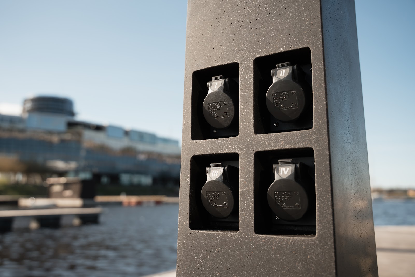
Choosing the appropriate pedestal involves understanding its core functionalities and how they match the marina’s specific needs. Marine power pedestals are designed to offer a range of amperage options, commonly including 20A, 30A, 50A, and 100A receptacles, to accommodate the diverse power demands of various vessel sizes. Some advanced units, like the HyPower PowerPort, can even offer capacities up to 400 amperes, capable of servicing multiple slips.
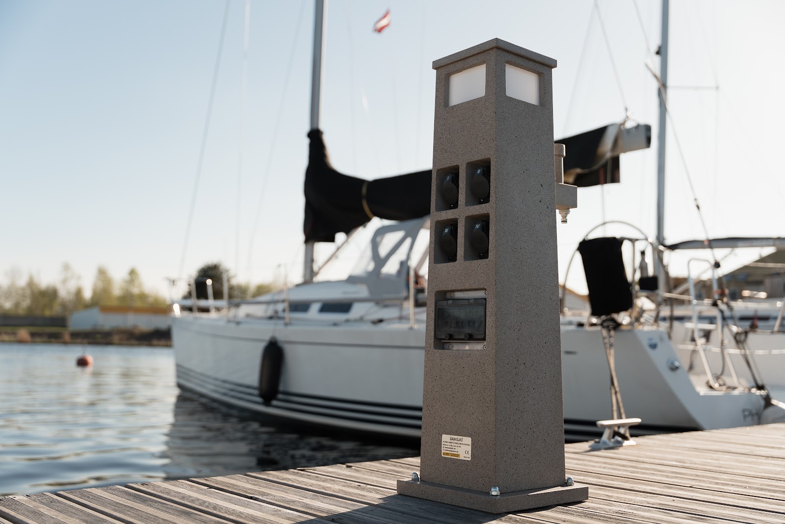
The construction material of the pedestal housing is a critical factor due to the harsh marine environment. High-quality pedestals typically feature housings made from corrosion-resistant materials such as 316L stainless steel 6 or robust, UV-resistant polycarbonate or polyurethane and polymer-concrete. This choice directly impacts the unit’s durability, resistance to saltwater corrosion, and overall lifespan.
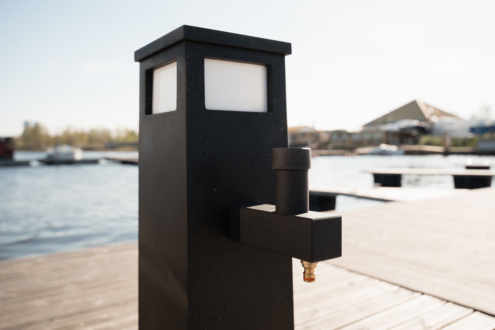
Modern pedestals often integrate multiple utilities beyond just power. Common features include water hookups, often with dedicated valves, and integrated lighting solutions. Lighting, such as 360-degree LED illumination controlled by photocells, enhances safety and visibility during nighttime operations. Optional connectors for CATV and internet access can further elevate the service offering for boaters.
Safety features are non-negotiable. Ground Fault Circuit Interrupters (GFCIs) are essential for protecting against electrical shock by quickly cutting off power if an imbalance is detected. Lockable, weatherproof doors are another vital feature, safeguarding circuit breakers and receptacles from the elements and unauthorized access. Some advanced pedestals may also incorporate smart technology, such as smart metering for precise utility usage tracking and remote monitoring capabilities, allowing operators to identify and address issues like outages or power surges promptly.
Decoding the Docks: Site Assessment and Power Requirements
A detailed site assessment is crucial. The primary step is to assess the needs of the vessels that will be using the slips to determine the appropriate power requirements. The power demands of boats vary significantly by size and type. For instance, smaller boats under 32 feet might only require 15-20A service, primarily for battery charging or small appliances, whereas larger yachts over 65 feet will typically need 100A service or more. Mismatching the pedestal’s capacity to the vessel’s load can lead to significant problems, such as overloaded circuits causing nuisance tripping and potential fire hazards, or conversely, investing in oversized, underutilized pedestals.
Table 1: Typical Power Needs by Vessel Size
| Boat Length | Typical Amperage |
| Less than 32ft | 15-20A |
| 32ft to 45ft | 30A |
| 45ft to 65ft | 50A |
| 65ft and up | 100A |
The dock layout itself influences pedestal placement. Considerations include ensuring easy accessibility for boaters, avoiding interference with mooring lines, and planning for efficient power distribution throughout the marina. Furthermore, the existing electrical infrastructure of the marina, including feeders and transformers, must be evaluated to confirm it can safely support the load of new or upgraded pedestals.
Safety First: Essential Tools, Safety Gear, and Understanding Key Regulations
Safety is the paramount concern in any electrical installation, especially in a marine setting. All electrical connection work must be performed by a qualified electrician who is thoroughly familiar with marine installations and all applicable codes and standards.
Several key regulations govern marine electrical installations:
- National Electrical Code (NEC) Article 555 (Marinas, Boatyards, and Commercial and Noncommercial Docking Facilities): This is the primary standard. It provides detailed requirements for wiring methods, equipment location, grounding, and GFCI protection.7 A critical concept within NEC Article 555 is the “electrical datum plane.” This plane is a specified height above the water level, below which most electrical components, including connections and receptacles, are prohibited to prevent submersion and associated hazards. The definition varies: for tidal areas, it’s 2 feet above the highest high tide; for non-tidal areas, 2 feet above the highest normal water level; and for floating piers, 30 inches above the water level at the pier and a minimum of 12 inches above the deck level.8 Adherence to this is not merely a regulatory formality but a fundamental design principle for ensuring safety against fluctuating water levels, thereby minimizing risks of submersion, corrosion, and short circuits. Electrical connections must also be located at least 12 inches above the deck of a pier.8
- NFPA 303 (Fire Protection Standard for Marinas and Boatyards): This standard provides comprehensive requirements aimed at protecting lives and property from fire and electrical hazards specific to marinas and related facilities. For example, the requirement for lockable weatherproof doors on pedestals, which protect breakers and receptacles, is stipulated by both NFPA 303 and NEC Article 555. This specific requirement illustrates a direct link between safety standards and practical operational security, preventing unauthorized access and shielding sensitive components from the harsh marine environment, thereby reducing risks like moisture ingress, a known cause of electrical faults.
- UL Certification: It is highly recommended to use pedestals that are UL-listed (Underwriters Laboratories). UL certification indicates that the product has been tested and meets specific safety and performance standards.
Equipping personnel with the correct tools and safety gear is also essential for a safe installation.
Table 2: Essential Tools & Safety Gear Checklist
| Category | Items |
| Tools | Drill, level, wrenches/socket set, wire strippers/crimpers, calibrated multimeter, screwdrivers, fish tape |
| Safety Gear | Insulated gloves (rated for the voltage), safety glasses/face shield, lockout/tagout (LOTO) kit, GFCI tester, appropriate non-conductive footwear |
Section 2: Setting the Stage: The Pedestal Installation Process
With thorough preparation complete, the focus shifts to the physical installation of the marine pedestal. This process demands precision, adherence to manufacturer instructions, and an unwavering commitment to safety.
Step 1: Unboxing and Inspection – What to Look For
Upon receiving the pedestal, the first step is to carefully unbox it and conduct a thorough inspection. Check for any signs of damage that may have occurred during shipping. It is crucial to verify that all components listed in the manufacturer’s packing list are present; referring to specific manufacturer manuals, such as those for HyPower or Eaton products, is essential here. Inspect the pedestal housing, receptacles, circuit breakers, and any internal wiring for visible defects or damage before proceeding.
Step 2: Mounting Your Pedestal – A Secure Foundation
A secure and stable mounting is critical for the pedestal’s longevity and safety.
- Surface Preparation: The dock surface where the pedestal will be mounted must be flat and level. If the surface is warped, such as with some wooden decking, or uneven, as can be the case with concrete, stainless steel washers should be used as shims to create a level base before tightening mounting bolts. Some pedestals, like the Bayside model, have protective coatings on their base to inhibit corrosion from treated lumber or concrete; care must be taken not to scrape or damage this coating during installation, as this could lead to corrosion problems and potentially void the warranty. The consistent recommendation across various installation guides to use stainless steel hardware and ensure proper surface preparation directly addresses the high risk of corrosion in marine environments. Failure to do so can lead to premature structural failure of the mounting, resulting in a loose or detached pedestal, which poses both an electrical and physical hazard.
- Mounting on Wooden Docks: For wooden docks, 3/8-inch stainless steel bolts with nuts and washers are typically used for through-bolting. Alternatively, 3/8-inch stainless steel lag bolts and washers can be used for surface mounting. Ensure bolts are of adequate length to securely anchor the pedestal.
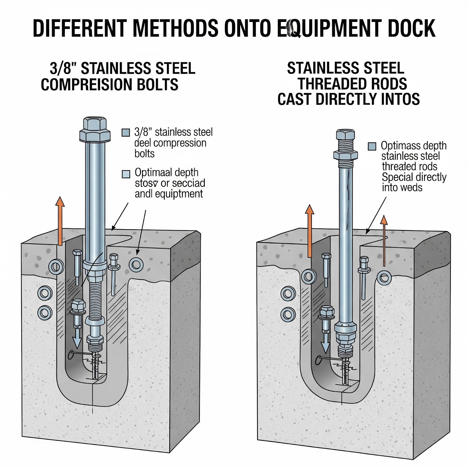
- Mounting on Concrete Docks: When mounting on concrete docks, 3/8-inch stainless steel compression bolts or stainless steel threaded rods cast directly into the concrete are the recommended methods.
- Hardware: Regardless of the dock type, always use stainless steel hardware (bolts, nuts, washers) for mounting. This prevents corrosion and ensures the long-term integrity of the installation.
- Orientation: The pedestal should be oriented so that its electrical access panel is easily accessible from the dock walkway. Crucially, ensure that the final placement does not interfere with vessel mooring lines.

Step 3: Powering Up – Electrical Connections
This is the most critical and potentially hazardous phase of the installation.
- CRITICAL SAFETY WARNING: Before beginning any electrical work, ALL power sources supplying the equipment MUST be disconnected and locked out/tagged out. This work must be performed by a qualified electrician. It is vital to understand that the circuit breakers on the pedestal unit itself DO NOT turn off the power supply to the unit’s internal bus bars; these can remain energized if the main supply is not disconnected.
- Accessing Terminals/Bus Bars: The method for accessing the electrical connection points varies by pedestal model. Some units, like the Eaton Powerhouse or Admiral SS, require removing screws and hinging or folding the top housing section down to expose the bus bar area. Other models may use removable access panels. The detailed instructions for accessing these components across different models highlight a trend towards modular designs, which can simplify installation and maintenance. However, they also underscore the absolute necessity of consulting the specific manufacturer’s manual for each model, as this guide provides general principles, while the manufacturer’s document is the definitive authority.
- Wiring: The qualified electrician will crimp appropriate wire terminations onto the supply lines and attach these leads to the pedestal’s bus bars or terminals as per the wiring diagram, which is often located inside the pedestal or provided in the installation manual. It is essential to use the correct wire size for the anticipated load; some manuals specify wire size limits, for instance, for loop feed configurations. All electrical connections must be tightened securely, as loose connections are a primary cause of overheating, voltage drops, and nuisance tripping. All electrical connections must be located at least 12 inches above the deck of a floating pier and must not be below the established electrical datum plane. This NEC requirement for connection height is a multi-layered safety measure. It not only protects against regular high water or tides (as defined by the datum plane) but also provides an essential buffer against wave action, minor storm surge, and reduces the likelihood of casual water splashes from rain or cleaning activities reaching critical electrical connections. This contributes significantly to the overall reliability and safety of the power supply.
- Grounding: Proper grounding is critical for safety. The equipment grounding conductor must be an insulated conductor, typically green or green with one or more yellow stripes, and sized in accordance with NEC 250.122, but not smaller than 12 AWG. This ensures a safe path for fault currents.
- Loop Feed: Some pedestals are designed for loop feed, where the main power supply conductors pass through the pedestal to energize subsequent pedestals in a parallel configuration. This requires careful attention to wire sizing and connection integrity at each point.
Step 4: Utility Hookups – Water, Data, and More
If the pedestal includes additional utilities, these are connected after the electrical power supply.
- Water Connection: This typically involves removing a designated access panel to reach the backside of the water valves or fittings, which are often 3/4-inch female NPT connections. A flexible stainless steel or black polyethylene hose is then connected from the marina’s waterline to the pedestal’s fitting. The hose should be carefully guided back into the base before reinstalling the access panel.
- CATV and Internet Connection: The process for connecting cable TV and internet lines is similar to the water connection. An access panel is removed, the service lines are pulled from under the base, and then connected to the backside of the respective jacks or assemblies within the pedestal. For some internet jacks, the individual wires within the cable may need to be separated and terminated according to the jack’s requirements.
Step 5: Final Assembly – Enclosing and Protecting
Once all connections are made and checked:
- Carefully guide all wires and hoses back into the pedestal base, ensuring they are not pinched or stressed.
- Reinstall all access panels, making sure they are securely fastened.
- If the top section of the pedestal was hinged open or removed, carefully fold it back onto the base and replace all retaining screws.
- Critically, ensure all weatherproof seals are correctly seated and that any doors close properly and can be locked, maintaining the enclosure’s integrity.
Section 3: System Checks and Going Live: Post-Installation
After the physical installation is complete, a series of rigorous system checks and tests must be performed by a qualified electrician before the pedestal is put into service. This phase is crucial for verifying safety and functionality. Skipping these vital steps can lead to immediate and dangerous consequences, negating all the careful work done during installation.
Conducting Essential Safety Tests (Qualified Electrician Recommended)
- GFCI Test: All Ground Fault Circuit Interrupter breakers and receptacles must be tested according to the manufacturer’s instructions to ensure they trip correctly when a fault is simulated. This is a critical life-safety check, verifying the primary protection against electrocution.
- Continuity and Polarity Checks: Using a multimeter, verify proper wiring continuity for all conductors, confirm that grounding paths are intact, and check the polarity of all receptacles. Incorrect polarity can damage vessel equipment and pose a safety risk.
- Voltage Checks: Confirm that the correct voltage is present at each receptacle under no-load conditions.
- Visual Inspection: Conduct a final thorough visual inspection of all connections to ensure they are tight. Check that no wires are pinched by covers or components and that all enclosures are securely fastened. Problems like loose connections or ground fault leakage, which can be identified during testing, are major causes of operational issues and hazards.
First Power-Up and Operational Checks
Once all safety checks have been satisfactorily completed by the qualified electrician:
- Energize the pedestal from the main supply panelboard.
- Lighting: If the pedestal is equipped with lighting, test its operation. For photocell-controlled lights, cover the photocell; the light should illuminate after a brief delay.
- Meters: If the pedestal has energy meters, check for proper display and ensure they are registering correctly.
Safely Connecting a Vessel to the New Pedestal
The correct procedure for connecting a vessel to shore power is an important user-side practice that complements a safe pedestal installation. Educating boaters on this sequence is a valuable follow-up to the installation itself.
- Ensure all circuit breakers on the pedestal are in the OFF position before attempting to connect a shore power cord.
- Connect the shore power cord first to the boat’s power inlet, ensuring it is properly seated and locked. Then, connect the other end of the cord to the appropriate receptacle on the pedestal, again ensuring a secure and locked connection. Connecting to an already energized pedestal receptacle can cause arcing, which can damage the plug and receptacle over time and poses a safety risk.
- Once both ends of the cord are securely connected, turn the corresponding pedestal circuit breaker to the ON position. The power indicator light on the boat, if equipped, should illuminate, confirming a successful connection.
Section 4: Smooth Sailing: Basic Pedestal Care and Maintenance
A successful installation is just the beginning. Regular care and preventative maintenance are essential for ensuring the long-term reliability, safety, and lifespan of marine power pedestals, especially given the demanding conditions they face. Proactive maintenance can prevent common issues such as nuisance tripping caused by corrosion or loose connections, and more severe problems like component failure due to neglected servicing.

Routine Inspection Tips (Monthly Recommended)
Regular visual inspections, ideally conducted monthly, can help identify potential issues before they escalate:
- Visually inspect the pedestal housing for any signs of physical damage, cracks, or corrosion.
- Check that all receptacles are clean and show no signs of burning, overheating, or excessive wear.
- Ensure that weatherproof doors and their seals are intact and functioning correctly to prevent moisture ingress.
- Verify that any integrated lighting is operational.
- Check all mounting hardware for tightness to ensure the pedestal remains securely fastened to the dock.
- An annual internal inspection, performed with the power disconnected by a qualified electrician, is also recommended. This should include examining bus bars for any signs of excessive heating or loose joints. Mechanical lugs, particularly those made of aluminum, are susceptible to galvanic corrosion and require close examination; if a set screw cannot be tightened, the lug should be replaced.
Cleaning and Preventative Measures
- Keep the area around the base of the pedestal clear of obstructions, debris, and accumulated salt.
- Address any minor corrosion or damage promptly to prevent it from worsening. Regular cleaning can significantly mitigate the buildup of corrosive agents.

Winterization Advice for Longevity (If applicable)
In climates where freezing temperatures occur, proper winterization is key:
- For pedestals with water systems, the system should be thoroughly purged with compressed air to remove all water. After draining, each ball valve should be opened and closed a few times to ensure any trapped water within the ball itself is expelled.
- Most modern marine power pedestals are constructed from materials designed to withstand year-round exposure to typical marine weather conditions. However, ensure all electrical components remain well-sealed and protected.
Conclusion
The journey from uncrating a new marine pedestal to seeing it safely power vessels at the quay is one that demands diligence, expertise, and an unwavering focus on safety. A successful installation is built upon a foundation of careful planning, including accurate site and needs assessment, selection of appropriate equipment, and a thorough understanding of and adherence to critical safety codes like NEC Article 555 and NFPA 303. Meticulous execution of each installation step, from secure mounting to precise electrical and utility connections, performed by qualified personnel, is non-negotiable. Finally, comprehensive post-installation testing verifies that the system is not only functional but, most importantly, safe for use.
However, the installation marks the beginning, not the end, of responsibility. Ensuring the long-term reliability and safety of marine power pedestals requires ongoing vigilance and a commitment to routine maintenance. Regular inspections, appropriate cleaning, and prompt attention to any signs of wear or damage are crucial for mitigating the risks inherent in providing electrical utilities in a harsh, wet, and often corrosive marine environment. Every aspect of a pedestal’s lifecycle—from material selection, compliance with electrical datum plane requirements, implementation of GFCI protection, use of corrosion-resistant hardware, to regular inspections—is designed to counteract these environmental challenges and electrical hazards. The potential consequences of neglect, ranging from inconvenient power interruptions to catastrophic equipment failures or safety incidents, underscore the importance of this comprehensive approach.
Ultimately, always prioritize safety and consult with qualified electricians or technicians when in doubt. While this guide provides general best practices, it is imperative to always consult and strictly follow the specific installation manual provided by the manufacturer for the particular pedestal model being installed. This ensures that all procedures align with the manufacturer’s design and safety specifications, leading to a truly secure and dependable power solution for the marina and its valued boaters.


